Another CPO: Cheaper Beeper

I’ve been busy plugging away at my DDS/Arduino/VFO for 630m (more on that later), however yesterday I came across a neat little circuit for a code practice oscillator.

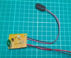
Cheaper Beeper CPO

Cheaper Beeper CPO

I’ve still got my previous CPO, however the simplicity of this one appealed to me. It’s two transistors, two resistors and a capacitor. All on a small piece of perf board.

In the image above, you can see the 9V battery connector. At the bottom are the two wires for audio out. And then in the middle there will be two more wires for the cw key. My plan it to mount it all in a small box with two 3.5mm mono ports – one for audio out and one for the key. That way I can either feed the audio into my computer for practice or into a speaker.

Close-up

Close-up

I’m thinking I may still build another CPO yet, as I really would like one with a sine wave – the square wave is a bit harsh and annoying. Plus, one with a sine wave I could wire into my FM rig for some code sending practice – if I find someone else so equipped. (I think sending the tone of these guys over the air would probably drive me and my practice partner nuts – not to mention anyone listening!)

Anyway, if you’d like to build one of these little guys yourself, the instructions can be found online here at the ARRL website. However, a word of caution.

There is a minor error in the schematic. If you’re rushing through trying to build the thing up quickly after work it may bring you unstuck – as it did to me. The PNP transistor in the schematic is marked as a 2n3904, however it is in the parts list as a 2n3906. Now a quick check would show that the correct one is the 2n3906, but if you just look at the schematic and go barging in blindly, well it wont work.

Anyway, enjoy! If you build one up send me a photo! 🙂

Sacrificial transistor - should've checked.

Sacrificial transistor – should’ve checked.

The Reverse Beacon Network

I remember a few years back hearing about the Reverse Beacon Network in a presentation given at CRARC. At the time I recall it seemed interesting, but then I was sidetracked by something else before I looked into it.

More recently I heard it mentioned in a discussion around (I think) the QRP Hours Contest on vkzlqrp mailing list. That got me thinking more and so I started reading and pondering.

RBN Home Page

RBN Home Page

The RBN is a simple idea, but like many simple ideas it’s a great one. People run their receivers (ideally SDR ones for wider bandwidth coverage, but even just a normal SSB receiver) feeding their input to their computer as they would for digital modes. Then they run CW Skimmer which monitors for CW signals – and specifically CQ calls with a callsign. Once these are detected, another piece of software (the RBN Aggregator) is used to feed these into the RBN network.

The ultimate result of all this, is that you can jump on a band of interest and send out a CW CQ call and see where in the world you’re making it to. Not too different to WSPR, however using an actual mode that you also use for QSO’s. Indeed, even people with no interest in RBN will still be detected just as a matter of using CW. In affect, it’s an automatic spotting database for CW.

So having my Softrock sitting around not doing much, I wondered about the potential of setting up and giving this a go. I still don’t have my HF antenna in place, but I do have my mini-whip. It seemed like a possibility.

I looked into CW Skimmer more and it looked straight forward enough. The only problem is that it’s commercial software. That is, after a 30 day trial period you have to pay – and not just some spare change. But at least with the 30 days I could see how it was and decide whether I wanted to do this long term and if so then consider paying. I do however, mean to do more of a search to see if there are any alternatives – but so far it seems not (and that’s possibly why there’s far fewer listeners on RBN than WSPR).

After downloading CW Skimmer and having a play, the following night I downloaded the RBN Aggregator and went about setting them up in unison. It was pretty straight forward, although the Aggregator has  changed it’s UI since the instructions on the website, and I did change a field only to find it would hang. But if I had of gone with the defaults it would have been a pretty simple affair.

VK7IS RBN Spots

VK7IS RBN Spots

To my amazement, in no time at all I was loading spots up to RBN. Albeit, I did have a couple of hiccups.

Firstly, my I/Q settings for my Softrock were back to front in CW Skimmer – so all my initial spots were around 7080kHz rather than 7010kHz. Secondly, I now know my Softrock is about 200Hz off, but I was able to fix this by adjusting the centre frequency in CW Skimmer.

Now, all appears to be going well. So the details of my setup are:

  • Receiver: Softrock Lite II (40m) – Listening to 96kHz with Audigy 4 sound card
  • Antenna: Mini-whip
  • Software: Windows XP SP3, CW Skimmer and RBN Aggregator

If you’d like to, you can view my spots on RBN. Hopefully I’ll be running for at least the next several days – depending on what else I’m doing. And whether I’ll do it long term, I’ll need to ponder whether it’s worth paying for CW Skimmer.

As you may see, I’m currently the only station listening from VK and there’s only one over in ZL. It’d be great if there were more down our way. I know of one other in VK1, but he’s currently moving house so is temporarily offline. I encourage people to give it a go – especially when you’re setup’s not in use.
Morse Code Resources

I’m still working away at learning my morse code. Practice kind of ended with the move to VK7 (as all things radio got a bit disrupted), but the last month or two it has resumed in earnest.

So I thought I’d share some of my current favourite resources that may be of use to others starting to learn or those more experienced looking to increase their speed.

I do a lot of my practice on the bus and at lunch in the library. So iPhone apps have been really useful. The main ones I use are:

  • Ham Morse – This is my main tool
  • Dah Dit – A useful tool, but probably goes against many principals of the Koch Method
  • MorseWords – A useful tool for words practice (especially seeing you can lock your phone and it will keep going)

As for online website tools, I’ve only really focused on one.

  • LCWO – Learn CW Online. Happens to be developed by one of the holders of 1000 cpm speed records and a very passionate CW op (that is, he also has an alarm clock he wrote that sends him his emails subject lines in morse code).

Computer software there is really only one I’ve used since I first thought of learning CW:

And finally some downloadable guides on how to learn/improve morse code:

Good luck to anyone out there using the above!

Beacon Keyer: Further Memory Optimisation

On the week-end I managed to further optimise my Beacon Keyer's memory use. It now looks like this:

AVR Memory Usage
—————-
Device: attiny13
Program:     712 bytes (69.5% Full)
(.text + .data + .bootloader)
Data:          6 bytes (9.4% Full)
(.data + .bss + .noinit)

The big item here is that 'Data' is now down to just 6 bytes! That is, the only data being represented is the string VK1IS plus it's null terminator – and also it happens to be using 2 byte alignment. This is due to placing all the look-up tables in PROGMEM.

Doing so is meant to add a little extra code, so in theory 'Program' should've also gone up (compared to back here when it was at 838 bytes). But at the same time I also removed a function I was using to control the PORTB pins and replaced it with two simple one line macros (one for key up, and one for key down). This simple change resulted in a good reduction in program size, and was an exercise is focusing on writing the code in the context of an MCU – rather than say a monolithic system. (Oh, and also included in this was a small bit of code to add an indicator LED for when the system is transmitting.)

Now in theory I can have the full string of "CQ CQ CQ DE VK1IS VK1IS VK1IS K". However I seem to be encountering an odd problem with the null terminator disappearing once the string gets to about 25 bytes long, so I need to look into this a bit more. Debugging MCU code is proving a learning experience in itself – as in this case the emulator does not seem to be working.

Anyway, once I sort that all out then I will consider it complete. Then hopefully I can return to my plans to play with the Arduino for a bit. 😉

Oh, and helping with all this (now being rigged up on a breadboard) is the little Sparkfun AVR Programming Adapter breakout board. For under $2, this little building block is gold!!

Arduino Arrived Today

Photo

In my playing with MCUs I finally decided to order an Arduino Uno. Originally I thought of them as a simple toy that would not equate to 'real' MCU programming, however I then realised (and it was pointed out to me) how close these are to the real thing and how great they'd be to get the basics of integration of components. To that end, I snapped one up pronto!

Today it arrived and I couldn't wait to finally attempt my first use of an LCD – in any form. Initially my plan was to try and use my LCD with an ATtiny2313, but it seemed like a bit of a way off as I'd also need to understand how to send the necessary raw data for the HD44780 protocol for an MCU. But the Arduino library has an LCD driver built in, so all I'd have to worry about is figuring out the wiring and just writing some very simple code. In other words, just learn the basics about how to connect up/integrate an LCD into a circuit and later I can focus on writing the low level code.

I'm happy to say, in my first night with my Arduino I succeeded in displaying text on an LCD within a couple of hours – and that was indeed after still making some wiring errors (thought I could skip the contrast control). To achieve the same result with a bare bones ATtiny2313 would have required significantly more effort – and when I stuffed up the wiring I wouldn't know if the problem was my code or the wiring. 😉

So, I look forward to building up a cool little radio project I have in mind that requires an LCD display and has an Arduino at it's core. Stay tuned, and consider grabbing yourself an Arduino – they're CHEAP and FUN!

CW Beacon Keyer Breadboarded

I managed to find a bit of time today and breadboard up my little CW Beacon Keyer with my ATtiny13. The idea was to simply have the MCU drive a NPN transistor to switch a key line. So  to that end, I simply wired up the circuit and then connected it to my CPO via the cable connected to my morse key. The video shows the result.

I'm pretty tickled, as this is my first MCU project so it was great to see it achieve what the intention was. It was also good that my CPO has an audio output that I can connect to my computer. With that, I ran FLdigi and it was great to see it had no trouble decoding the morse.

In the video you may also note the little SparkFun Breadboard Power Supply Stick I'm using. This provides a nice easy switchable 5V/3.3V and at the price was more convenient than me putting together a small board with just a 5V regulator. I ordered it from ProtoGear and had it on Friday just in time for the week-end. This will be rather useful for prototyping MCU and other TTL IC circuits on the breadboard.

Next step now is to draw up the simple circuit diagram and put together the full keyer – although that will also have an ISP connector. Might be harder to find time to achieve this next step though, but hey, at least the ideas there. 😉

CW Beacon Keyer V2

I’ve re-written (or, generated from my old ones) the character look-up tables and thereby the resulting encoding functions. Further, I then re-wrote the MCU control code to use the new encoding and wow! what a difference.

All now fits on a ATtiny13 (1K flash, 64B SRAM) as long as I keep the transmitted text to no more than 7 characters (more than enough for VK1IS) – keeping in mind the ATtiny13s only have 64bytes of SRAM (which also needs to store the lookup tables).

So here’s the stats when using the string ‘VK1IS’:

The old:

AVR Memory Usage
----------------
Device: attiny85
Program:    2000 bytes (24.4% Full)
(.text + .data + .bootloader)
Data:        240 bytes (46.9% Full)
(.data + .bss + .noinit)

The new:

AVR Memory Usage
----------------
Device: attiny85
Program:     838 bytes (10.2% Full)
(.text + .data + .bootloader)
Data:         48 bytes (9.4% Full)
(.data + .bss + .noinit)

As you can see, there are huge savings being made there. This is due to two key things:

  1. (SRAM) Encoding each character in 8 bits (where as previously letters were using some 5 or more BYTES each); and
  2. (Flash / Program) No longer using libc as I can encode the result in place – no need for a resulting dynamically allocated encode byte array.

This improvement also means I can now happily have an ATtiny85 send the full ‘CQ CQ CQ DE VK1IS VK1IS VK1IS K’.

There are more memory improvements that could be made to allow the ATtiny13 to support longer strings. Being coded in C, I can use the PROGMEM directive on the look-up tables so that they’re not stored in SRAM. This could result in a SRAM saving of about another 41 bytes – meaning in the above tables it would read ‘Data: 7 bytes’ (very nice). Might look into this soon.

For now though, I have a rather flexible solution for creating AVR based beacon keyers – and indeed keyers in general. I now might see if I can breadboard the basic circuit (time permitting) and hook up to my CPO. As I sit here I have a little ATtiny13 in my basic dev board flashing out VK1IS at QRSS1 speed.

Oh one thing that surprised me switching from the 85 to the 13 was the clock speed. You see both use the CKDIV8 fuse by default to divide the internal oscillator, however the 85 has an internal oscillator of 8MHz, however the 13 has an internal oscillator of 9MHz. This needs to be noted to ensure that the timings for my morse generation remain somewhat accurate.

MCU Memory Constraints and Morse Encoding

In my previous post about completing my initial code for my MCU based beacon keyer I made mention to the use of memory. Indeed, my code was of such size I had to use the largest AVR ATtiny chip I could (well, memory wise). The ATtiny85 gave me a whopping 512 bytes of SRAM – and 512 of EEPROM and 8KB of flash. Who could ever need more than that right!

Sending just my callsign (VK1IS) worked fine with my code running on this MCU, however last night I thought I'd try the longer string of:
CQ CQ CQ DE VK1IS VK1IS VK1IS K

Could be useful for common CW comms.

Unfortunately, that resulted in the chip running out of memory when it got the third iteration of my callsign. With compile time memory usage being up at 260 bytes with this string; then the need for memory for active instructions; and then finally the dynamically allocated memory to store the encoded version of that string; there simply wasn't enough space. Indeed, with my current encoding method, to encode that string required more than 150 bytes and that was more than was available (after the 260 bytes at compile time and active instructions). (Note here, my look-up tables – by manual calculations – require 223 bytes!!)

So, it seems I should do some memory optimisations after all.

Conveniently, I received an email from Owen this morning (VK1OD) informing me that it is possible to encode all Morse characters in 8 bits. So after a bit of pondering I realised this would be possible by just using (for example) 1 for dit and 0 for dah. But seeing it's variable length what do you use for a marker for the start. In trying to figure this out, eventually I decided to be lazy and search the web. That search revealed this:

Seems all I need is to just mark the start of a sequence with a 1:

The format of each Morse character is as follows: Zero or more 0 bits, followed by a single 1 bit, followed by the Morse Code representation of the character in binary, with a 0 indicating a dit and a 1 indicating a dah.

That first "single 1 bit" is what then marks the start.

With this method one can definitely encode all 41 characters in the Koch set plus a good number of prosigns (AR, KN, etc.). As time permits I think I'll look at writing another cw library to implement this. Big memory will be saved – about 75% – and maybe I'll look to see if I bother with an intermediary encoding of the string or not (I have some ideas on how to deal with that to save significant memory.) Maybe it'll fit on an ATtiny13 yet (64 bytes of SRAM, 64 bytes of EEPROM and 1KB of Flash).

While looking at this I also looked at the code for the Freakin Beacon. It seems rather than a look-up table they've gone down the path of a subroutine for every character. This would save on SRAM, but then the code size would be bigger. I may also consider looking at this as another option – should be able to generate the code for this from my current CW library. 😉

CW Beacon Keyer

You might be wondering why activity has been a bit minimal lately. Well, our first child was born almost one month ago now so I’ve been a tad busy. 😉 I’ve got a couple of more things coming up soon, but hopefully activity will resume in the next month or two. 🙂

That said, in the meantime I’m reading and where possibly playing with simpler things.

For example, some months ago I decided to start looking into microcontrollers. I pondered between AVR and PIC and in the end with with AVR. So I grabbed myself an AVRISP mkII and a few ATtiny chips and built up a basic development board following instructions on I Make Projects. Within a short time I had a flashing LED but then got busy.

Anyway, I had decided a great first MCU project would be a CW Keyer (mainly for QRSS on LF, but also wherever else). These can be implemented many ways (and indeed, there’s many bits of code one could download) and many simply hardcode the sequence for the callsign. However, I wanted to learn and build from scratch – plus it was a great opportunity to do some C programming.

To that end I decided to write up a library that would provide encoding of a string into a CW element sequence. I could then enumerate over this sequence generating the matching delays for the key-ups and key-downs. Further, I did calculations based on the PARIS methodology for the element durations for various common speeds covering 5WPM to 40WPM and QRSS1 to QRSS60. I initially wrote the library and unit tests on the PC with GCC, and then when it was ready just added it into an AVR Studio 5 solution.

With such a library, the resulting MCU specific code was minimal and I have two ‘configuration’ variables – one for speed and one for the string to send.

Yesterday I got this all working and successfully tested on my dev board with an LED. Doing so I learnt several things such as _delay_ms() requires a constant parameter and more significant how to use the AVR Studio simulator – very handy tool.

Oh, I also came to better appreciate the minimal memory contraints of the ATtiny chips. In the end my program had to be run on an ATtiny85 (although it may fit on a ATtiny45), this is due to the encoding library and it’s look-up tables being on the chip. This results in AVR studio stating SRAM usage of 240 bytes (ATtiny45 has 256 and ATtiny85 has 512). Strictly speaking there is no need for the encoding library on the chip so you could go smaller – you could run it on a PC, grab the encoded array and place it on the EEPROM and have it read from there. But hey, for now this is okay me thinks.

So the video shows the result with an LED flashing out my callsign at 5WPM. From here I just need to whip together a small number of components to have a nice standalone beacon/QRSS keyer – however, not entirely sure when I’ll have the time for this. When that’s done, I’ll be sure to share all. 🙂

CW Prosigns and RST

While trying to learn my CW ready for TX and RX, I'm finding there are a number of CW prosigns that I've not really come across before. Ones such as BT, AR and VA. In my search for these I've come across this site:

Also, in CW it's interested me that for signal reports they use the whole RST (not just RS like for voice). I've always wondered what is trying to be achieved with the Tone element of RST, so for that I've come across this:

From that I can see why most the time a T of 9 is sent. However, it is useful to see there are non-numeric options for the T value such as X, C and K.